Film Path
The Film Path is the route that the film takes through the projectors whilst being projected. As such, it is imperative that all projectionists know this in detail, as any incorrect lacing can result in a loss of presentation quality and even cause significant damage to the film itself.
Warwick Student Cinema operates two Cinemeccanica Victoria 8 combined 35mm/70mm projectors. The lacing is identical on each and the focus here shall be on the lacing of 35mm film.
Standard Lacing
All 35mm films need to be projected with the soundtrack towards you. If the film has been made-up correctly then this will result in the film coming off the top of the pay-out spool.
For a Dolby Digital (SRD), Stereo (SR) or Mono film, the film then passes down the left hand side of both of the 35mm/70mm combined rollers of the SDDS unit. The next roller used is the top left roller of the DTS unit, after which the film passes to the joint 35mm/70mm roller at the top of the projector casing.
Within the Projector
From the point of entry to the projector, lacing is identical for all 35mm films, regardless of the picture format and sound system used. Details of lacing above the casing will be given below for DTS and SDDS soundtracks.
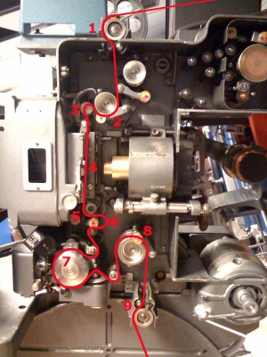
The image to the right shows one of the projectors, with a red line indicating the film path from the first roller at the entrance to the casing, to the last roller before the take-up spool. The numbered sections are the following:
1. The entry roller to the projector casing. This is a dual 35mm/70mm roller, so you must check that the 35mm film is sitting in the 35mm groove.
2. The first sprockets and arm. The film needs to properly on the sprockets. Once laced, tension the pay-out reel. If you open the arm the film should remain stationary, indicating that it is nicely on the sprockets. If the film is not on the sprockets properly, then opening this arm will cause the film to move. Adjustments at these sprockets determine the size of the top loop. The arm must be closed when projecting.
3. The top loop is key in several ways. It is important to have this the right size (the qualified projectionist will show you this!) in order to keep the picture and sound in sync if playing in DTS or SDDS. Also, this loop trips the safety arm above it if the film snaps at the top of the gate.
4. The film passes through the gate between the runners and the back-plate. It must be sitting smoothly between the two if it is to run without problems.
5. The intermittant. This is sprocket that pulls through whole frames of film at a time. It must be set before positioning the film in the gate, so that it is about to pull the film down by a frame. The arm must be closed when projecting.
6. The bottom loop (size to be shown by the projectionist) must be correct once the intermittant has been set. This is required for sync of sound (SRD or SR) with picture, and the smooth running of the film. If the loop is too small then the sound will be scratchy.
7. The film wraps around the large silver bell, and it is here that the Dolby Digital and Stereo soundtracks are read. The film must be sitting in the 35mm groove, beneath the liftable arm.
8. The last sprockets before the film exits the projector casing. Adjustments at these sprockets determine the size of the bottom loop.
9. The film exits down the left hand side of this roller before wrapping around the take up spool.
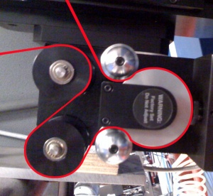
DTS
After coming off the take-up spool, the film goes over the top roller before passing down the left hand side of both of the 35mm/70mm combined rollers of the SDDS unit, as per lacing for SRD or SR.
The lacing for DTS is shown in the diagram to the right.
SDDS
After coming off the take-up spool, the film goes over the top roller before getting to the SDDS unit. The first and last rollers of the unit are both 35mm/70mm combined rollers which are normally passed on the left when not lacing SDDS.
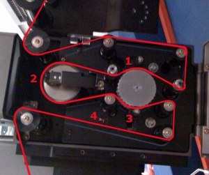
SDDS is laced as per the image to the right (which mimics the blue line on the units), with the following key points:
1. The top arm must be closed with the film properly on the sprockets. This is used to set the tension level.
2. The film must go around this roller with both of its edges slightly protruding from the roller. This is due to the sound readers for each of the two SDDS strips being placed here, to read the code on the edges of the film.
3. The bottom arm must be closed with the film properly on the sprockets. This is used to set the tension level.
4. The tension level is an indicator of whether or not the tension is correct when passing around the SDDS reader (LEDs located at roller - 2.). The line moves up and down dependent upon the amount of film between the top arm and bottom arm and the film should be adjusted at these arms until the movable red line is level with the tip of the red triangle.
After leaving the SDDS unit, the film must loop around the top DTS roller before entering the projector casing. Failure to do this will result in the picture and sound being out of sync, as well as the likely scratching of the film on the edge of the SDDS unit.


